Replica Ekco A22T
-
1. Introduction
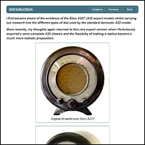
I first became aware of the existence of the Ekco A22T (A22 export model) whilst carrying out research into the different types of dial used by the standard domestic A22 model.
More recently, my thoughts again returned to this rare export version when I fortuitously acquired a semi-complete A22 chassis and the feasibilty of making a replica became a..... -
2. Creating the dial
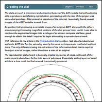
The dials are such a prominent and attractive feature of the A22 models that without being able to produce a satisfactory reproduction, proceeding with the rest of the project was somewhat pointless. After extensive searches of the internet, I eventually found several images of the A22T suitable to work from. An auction listing showing a complete image.....
-
3. Calculating the LC tank components
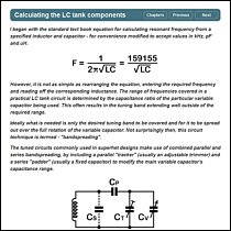
I began with the standard text book equation for calculating resonant frequency from a specified inductor and capacitor - for convenience modified to accept values in kHz, pF and uH. However, it is not as simple as rearranging the equation, entering the required frequency and reading off the corresponding inductance. The range of frequencies.....
-
4. Winding the SW coils
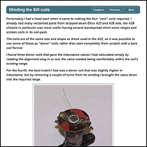
Fortunately I had a head start when it came to making the four "new" coils required. I already had many reclaimed parts from stripped down Ekco A23 and A28 sets, the A28 chassis in particular was most useful having several bandspread short wave ranges and sixteen coils in its coil-pack.
The coils are of the same overall size and shape as..... -
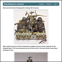
5. Rebuilding the coil-pack
Next came the task of stripping the existing A22 coil-pack. After careful removal of all the components I added an extra trimmer capacitor to the stripped board. This was necessary due to all three coils in the aerial section requiring a tracking trimmer. As the coil-pack in an original A22T also has this sixth trimmer, I adopted the same layout. I modified the.....
-
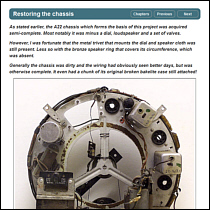
6. Restoring the chassis
As stated earlier, the A22 chassis which forms the basis of this project was acquired semi-complete. Most notably it was minus a dial, loudspeaker and a set of valves. However, I was fortunate that the metal trivet that mounts the dial and speaker cloth was still present. Less so with the bronze speaker ring that covers its circumference, which was.....
-
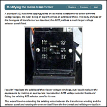
7. Modifying the mains transformer
A standard A22 has three tapping points on its mains transformer to select different voltage ranges, the A22T being an export set has an additional three. The body and size of the two types of transformer are identical, the A22T just has a much larger voltage selector panel fitted. I couldn't replicate the additional three lower voltage.....
-
8. Initial testing and alignment
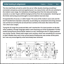
The time had finally arrived to switch the set on! After double checking everything I connected a temporary aerial and applied power via a lamp limiter with the set switched to the medium wave range. No indications of anything amiss from the lamp and twenty seconds or so later I'd got a definite background hiss from the loudspeaker. Switching out.....
-
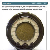
9. Conclusion
This project pushed me further than any other restoration I had previously undertaken. I broke into new ground in terms of calculating/making the coils and rebuilding the coil-pack for this set - something I hadn't even contemplated attempting before. In the final analysis, I considered the extra effort made early on in the project was well.....
Copyright © Robert Darwent · All rights reserved · E&OE · www.wavesintheair.co.uk online since 2015