3. Calculating the LC tank components
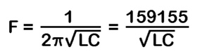
I began with the standard text book equation for calculating resonant frequency from a specified inductor and capacitor - modified so as to accept values in kHz, pF and uH.
However, it is not as simple as rearranging the equation, entering the required frequency and reading off the corresponding inductance. The range of frequencies covered in a practical LC tank circuit is determined by the capacitance ratio of the particular variable capacitor being used. This often results in the tuning band extending well outside of the required range.
Ideally what is needed is only the desired tuning band to be covered and for it to be spread out over the full rotation of the variable capacitor. Not surprisingly then, this circuit technique is termed - "bandspreading".
The tuned circuits commonly used in superhet designs make use of combined parallel and series bandspreading, by including a parallel "tracker" (usually an adjustable trimmer) and a series "padder" (usually a fixed capacitor) to modify the main variable capacitor's capacitance range.
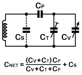
In the generalised LC tank circuit - CV represents the variable capacitor, CT the tracker (trimmer), CP the padder and CS is any stray circuit capacitance present. Combining all these components gives an overall "net" capacitance with which the inductance is tuned to resonance.
If your interested in delving deeper into the subject of bandspreading, paying a visit to Robert Weaver's excellent website - Bob's Electron Bunker is well worth your time. I referred extensively to the in-depth explanation of the mathematics involved and made use of the on-line resonance calculators available.
Normally a LC tank circuit is designed to cover a desired tuning range, once built a tuning dial is then made to tally with specific frequency points. Unfortunately, my problem was the exact opposite. I already had the dial marked with specific frequency points, for which I needed to design LC tank circuits to track those points with a high degree of accuracy.
To begin to solve the problem, I temporarily fitted a test print of my A22T reproduction dial to the chassis and rigged up a suitable power supply for the illuminated tuning arm. Whilst accurately placing the tuning cursor on the major frequency markers on the dial, I noted down the corresponding capacitance reading from a digital LC meter I had connected across the main tuning capacitor. Repeating this procedure for both short wave ranges, I obtained the specific capacitance value that produced a known frequency at many points across the dial.
I now needed to try, by trial and error, various values for inductance, tracker and padder that best matched all of the required frequency points as accurately as possible using the previously stated equations. It will be appreciated that many combinations of values needed to be searched through. To do so by hand with only a pocket calculator would have taken a very long time, instead I wrote a small computer program to do the "number-crunching" for me. Even so, it still took the computer several hours of continuous calculations for each short wave range to arrive at the best match having the lowest error difference between required frequency and calculated frequency.
Surprisingly, the final values found produced a maximum error of a fraction of one percent across all required frequency points for both aerial and oscillator tank circuits on both short wave ranges. More than accurate enough for my purposes, even allowing for the inevitable errors involved in positioning the tuning arm accurately on a dial frequency point and in the accuracy of measurement of capacitance by the LC meter. The final results are presented in tabular form.
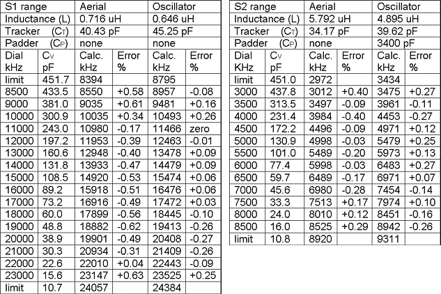
Note; in both tables the calculated frequency values under the "Oscillator" heading are higher than the specified "Dial" frequency points or the calculated frequency values under the "Aerial" heading due to the addition of the 465 kHz intermediate frequency.
At first glance some of those frequency errors may seem quite large, for example; the largest error on the S1 Aerial table is at the 23000 kHz point which actually comes out at 23147 kHz in the calculations. In reality the 147 kHz difference equates to roughly the thickness of the tuning pointer shadow produced by the illuminated tuning arm - more than acceptable in practice.