4. Winding the SW coils
Fortunately I had a head start when it came to making the four "new" coils required. I already had many reclaimed parts from stripped down Ekco A23 and A28 sets, the A28 chassis in particular was most useful having several bandspread short wave ranges and sixteen coils in its coil-pack.
The coils are of the same size and shape as those used in the A22, so it was possible to use some of those as "donor" coils rather than start completely from scratch with a bare coil former.
I found three donor coils that gave the inductance values I had calculated simply by rotating the alignment slug in or out, the value needed being comfortably within the coil's existing range.
For the fourth, the best match I had was a donor coil that was slightly higher in inductance, but by removing a couple of turns from its winding I brought the value down into the required range.
It was a simple matter to remove most of the wax sealing the coil winding with a soldering iron, unsolder one end and take off a couple of turns. I ensured that enough wax was left on the winding to keep the other turns firmly in place whilst carrying out this operation.
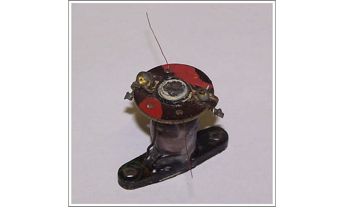
Each of the four coils now needed a coupling winding adding over the main inductance winding. From unwinding a spare coil, I determined that this coupling winding consisted of approximately five to six turns evenly spaced on top of the main winding.
Using a similar gauge enameled copper wire, I carefully added this coupling winding. Each end of the winding was terminated by feeding through unused holes in the top of the former. After securing the ends to solder-tags to provide a connection point, the coil was resealed with wax to keep everything stable.