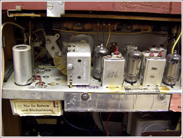
4. Chassis Restoration
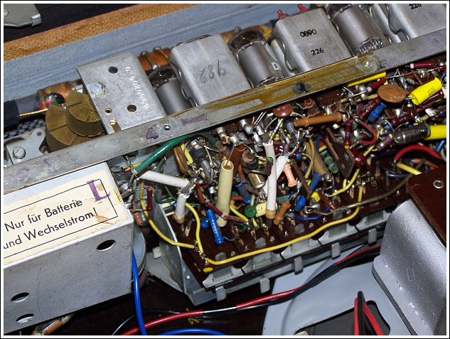
Virtually every one of the dozen or so wires going between the main chassis and power supply board had been disturbed - several of the wires having been left disconnected.
It took quite some time to track and trace everything, but gradually I got the wiring reinstated to how it would have been originally.
Finally, I had reached the point when I could safely apply power for the first time - I connected 90 volt and 1.5 volt bench power supplies and switched on.
I was greeted by fairly decent quality audio coming from the loudspeaker on the VHF position, most of the other bands appeared to be working too when tried.
The MW position appeared to be completely dead though, but I hoped this was just down to dirty switch contacts on that band which later proved to be the case.
A current check in the HT supply showed the set to be drawing around 37mA instead of the expected 12 to 15 mA as stated in the schematics - something was definitely amiss somewhere, most likely several leaking capacitors.
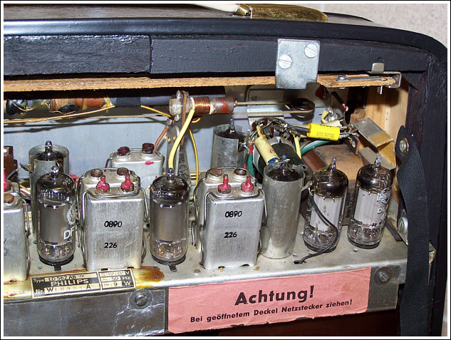
I began the job of "re-capping", which isn't a quick or easy task with this set - there are around 90 capacitors in total, a few dozen of which are paper/wax types along with perhaps another half-dozen electrolytics.
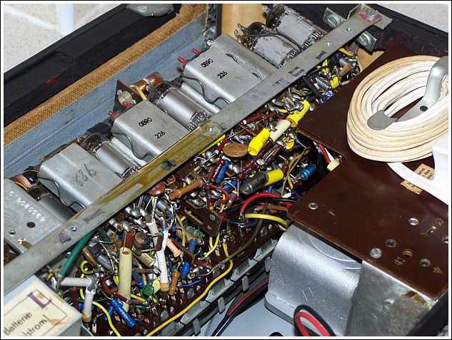
The sheer density of the components and wiring underneath the chassis made for slow progress, but I eventually removed all the suspect capacitors and replaced them with either new polypropylene types or electrolytics as appropriate.
All the paper/wax types removed and tested were found to be leaking to some degree or other - the electrolytics when tested seemed to be fine but I replaced them anyway.
After changing each group of capacitors I checked the HT current again, and it was steadily dropping towards the correct range. However, when capacitor replacement was complete the current still stubbornly remained at around 19 to 22 mA despite everything obvious having been changed.
After much "head-scratching" I tried replacing the DF97 employed as the oscillator valve - immediately the HT current consumption dropped to 9 to 11 mA.
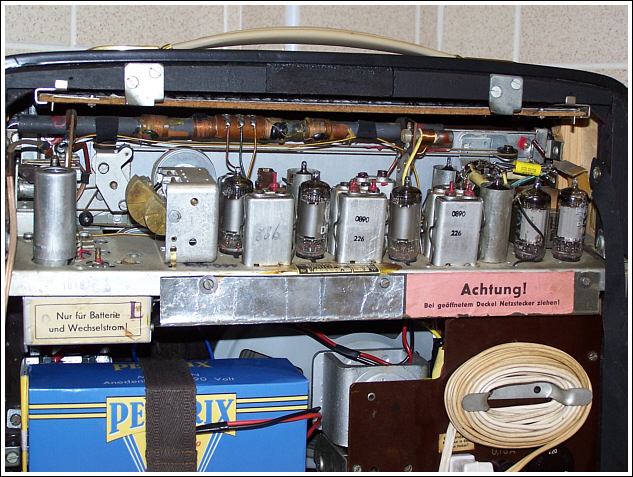
With hindsight I really should have suspected the valve sooner, as every other component involved with the bias-line to the output stage had either been checked good or replaced - since the set appeared to be working so well, other than the HT current issue, I had wrongly given the valve the benefit of the doubt that it was the culprit.