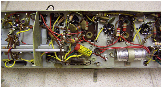
2. Fault finding the chassis
I connected up HT 90v and LT 1.5v power supplies and switched the set on for the first time - there was no signs of life. No crackles when the wavechange switch or volume control was operated - it appeared absolutely dead.
Voltage checks showed HT and LT to be reaching all six valves correctly. Testing each valve one at time in another working set proved each to be still OK.
Continuity and resistance tests showed all of the switch contacts in the set to be OK and also both the output transformer and loudspeaker to be fine.
I connected my signal generator at the IF frequency of the set to each of the valve grids in turn but got no sound from the speaker at all - the set remained absolutely lifeless.
I began to suspect a contact problem with the valve sockets so decided to measure the total LT current being drawn. It was only at 95mA when the expected figure was 175mA - clearly at least two of the valves were not receiving the LT supply.
Removing each valve in turn whilst watching the current reading proved valve V4 (DAF96) and V6 (DL96) were not drawing current.
A close inspection of those two valve sockets showed at least a couple of loose pins in each. Attempts to re-tensioning them with a needle was ineffective and indicated some of the forks on the pins to be broken.
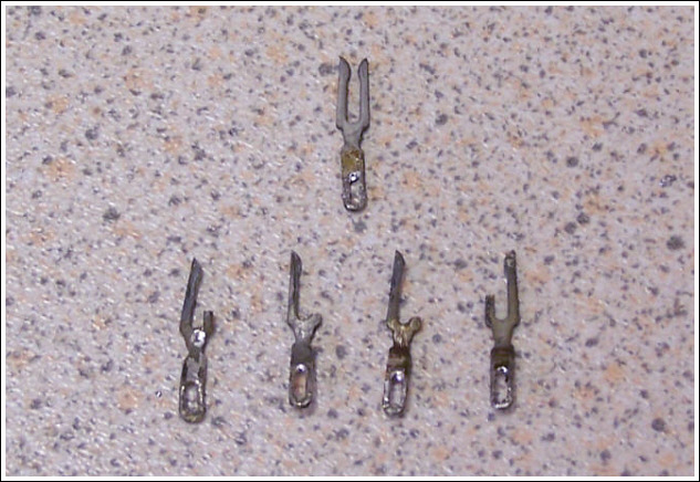
Fortunately the set uses a type of socket which have push through pins - so a complete replacement was not necessary and I was able to de-solder and temporarily remove all the wiring and components from the affected pins, push them out with pliers and insert unbroken pins from spare sockets I had to hand.
I had to replace 3 pins in the V4 socket, 2 pins in the V5 socket, and 2 pins in the V6 socket. All were in the same condition - one of the two forks broken.
After changing all the coupling and de-coupling capacitors, especially around the V5 and V6 valves, I tried the set again. This time good reception and performance on MW and LW - VHF was also working but stations were noticeably quieter.
The set uses DF97's in postions V1 to V4 - as an experiment I transposed the V1 and V4 valves. There was an immediate improvement to the VHF reception - stations came in loud and clear with excellent audio quality.
I assume the original V1 valve just wasn't up to dealing with the high frequencies anymore but still OK at MW and LW wavelengths - and obviously as an IF frequency amplifier which position that valve now occupied on the chassis.
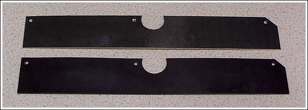
I turned my attention to replacing the warped paxolin board mentioned earlier. Using a piece of basewood of the correct thickness - I scanned the paxolin board, which has several alignment markers on it, and printed the image on to paper. This was then glued to the basewood and everything carefully cut out with a craft knife.